Given the complexity of the topic, we have prepared two versions for this entry:
The short version is available below. If you'd like to learn more, the extended version is available after the short version, with lots of in-depth information.
SHORT VERSION
BALLISTIC CALCULATOR: HOW IT WORKS
The trajectory becomes prediction
A ballistics calculator is a program that predicts the behavior of a projectile after it leaves the barrel. It combines data from the weapon, ammunition, optics, and the environment to estimate drop, windage, residual velocity, energy, and time of flight. The solution can be expressed in MRAD, MOA, clicks, or centimeters and applied via turrets or reticle references. It doesn't automatically indicate where each shot will land: it produces a mathematical prediction that must be built with realistic data and verified on target.
In short (Italian only)
- What is it: a software that calculates the projectile's predicted trajectory.
- What data does it use: speed, ballistic coefficient, zeroing, atmosphere, distance and wind.
- What it gives back: vertical and lateral corrections, speed, energy and flight time.
- Where is it: apps, rangefinders, binoculars, viewers, and dedicated devices.
- What is the limit: Inaccurate data produces seemingly precise but incorrect solutions.
How the trajectory is calculated
After exiting the muzzle, the projectile is subjected primarily to gravity and air resistance. The calculator divides the flight into numerous intervals and determines, for each of them, the velocity, deceleration, and position.
The resulting trajectory is compared to the aiming line , taking into account the height of the scope and the zeroing distance. The program then determines the correction needed to bring the aiming point back to the predicted impact position.
Gravity takes effect from the moment the bullet leaves the barrel. If the trajectory initially appears to be rising relative to the line of sight, it's because the barrel axis is oriented slightly upward relative to the scope axis.
The essential data
| Date | Function |
|---|---|
| Initial speed | Determines the starting point of the calculation and influences the flight time |
| Ballistic coefficient | Describes the ability of the projectile to maintain velocity |
| Height of the optics | Defines the distance between the barrel axis and the sight line |
| Zeroing distance | Establishes the point at which aim and midpoint of impact coincide |
| Condizioni atmosferiche | They allow you to calculate the density of the air |
| Distance and inclination | They describe the geometric position of the target |
| Wind | Allows you to estimate lateral displacement |
Initial velocity and chronograph
The velocity listed on the ammunition package is obtained with a specific test barrel. Your rifle may produce a different value due to barrel length, chamber tolerances, temperature, and production batch.
To obtain reliable data, it is advisable to use a chronograph and calculate the average velocity of a series of shots. A single reading may not represent the actual behavior of the ammunition.
Shot-to-shot consistency is especially important at long ranges: marked variations in velocity produce differences in flight time and can widen the vertical dispersion.
The ballistic coefficient
The ballistic coefficient , abbreviated BC, describes how effectively a projectile maintains velocity compared to a standard shape. A higher value generally indicates less deceleration, but must be associated with the correct model.
The G1 model uses a bullet with a relatively short nose and a flat base as a reference. The G7 model is often better suited to modern, elongated bullets with a tapered base. The two values are not interchangeable.
More advanced programs can use custom curves derived from Doppler measurements. These directly describe the deceleration of a specific projectile in different velocity regimes.
Atmosphere and air density
Temperature, pressure, and humidity determine the density of air. A denser atmosphere increases the resistance encountered by the projectile; less dense air allows it to maintain its velocity better.
It's important to distinguish between absolute pressure, actually measured at the location of use, and the sea level-corrected pressure used in weather reports. Simultaneously entering absolute pressure and altitude into a program that doesn't require it can double-count the altitude effect.
Humidity generally has a minor influence. Contrary to popular belief, humid air is slightly less dense than dry air at the same temperature and pressure.
Wind evaluation
Wind is often the most difficult variable to input correctly. The computer can accurately calculate speed and direction, but it can't know what's happening along the trajectory if the data provided doesn't represent real conditions.
An anemometer measures the wind at the shooter's position. Terrain, vegetation, rocks, and elevation differences can, however, affect the wind between the starting point and the target.
The lateral solution must therefore be interpreted as the mathematical consequence of the inserted wind, not as a complete measurement of the entire path.
End of the first part of the summary version.
Slanted shot and equivalent distance
When the target is above or below the shooter, the distance measured along the line of sight does not coincide with the horizontal component. The required vertical correction is generally less than that required for the same distance on flat ground.
Rangefinders equipped with an inclinometer can provide an equivalent ballistic range or transmit linear range and angle of elevation to the computer. Linear range remains important because it describes the actual path taken by the projectile and affects flight time, velocity loss, and wind action.
What results does it provide?
After processing the data, the calculator can show:
- vertical correction to compensate for the trajectory;
- lateral correction for wind and gyroscopic effects;
- number of clicks to be applied to the turrets;
- grid reference to use;
- residual speed and energy at the selected distance;
- flight time;
- Mach number and possible entry into the transonic region.
In practical use, it is essential to always check the correction unit. A value expressed in MRAD cannot be directly applied to a turret graduated in MOA.
MRAD, MOA and click
| Regulation | Move 100 meters | Move 300 meters |
|---|---|---|
| 1 MRAD | 10 cm | 30 cm |
| 0,1 MRAD | 1 cm | 3 cm |
| 1 MOA | About 2,91 cm | About 8,73 cm |
| ¼ MOA | About 0,73 cm | About 2,18 cm |
If the program indicates a correction of 2,4 MRAD and the turret has 0,1 MRAD clicks, 24 clicks are needed. With a correction of 6 MOA and a ¼ MOA turret, 24 clicks are also needed.
Correct with turrets or reticle
The solution can be applied by rotating the elevation turret or using the reticle graduations. The turret allows you to keep the center of the crosshair at the desired point; the reticle, on the other hand, allows for immediate compensation without changing the mechanical zero.
In the first focal plane, the graduations maintain their value at any magnification. In the second focal plane, they are generally corrected only to the power indicated by the manufacturer.
The reticle, turrets, and calculator should all use the same unit. A fully MRAD or MOA system makes it quicker to read and apply the solution.
Calculator and laser rangefinder
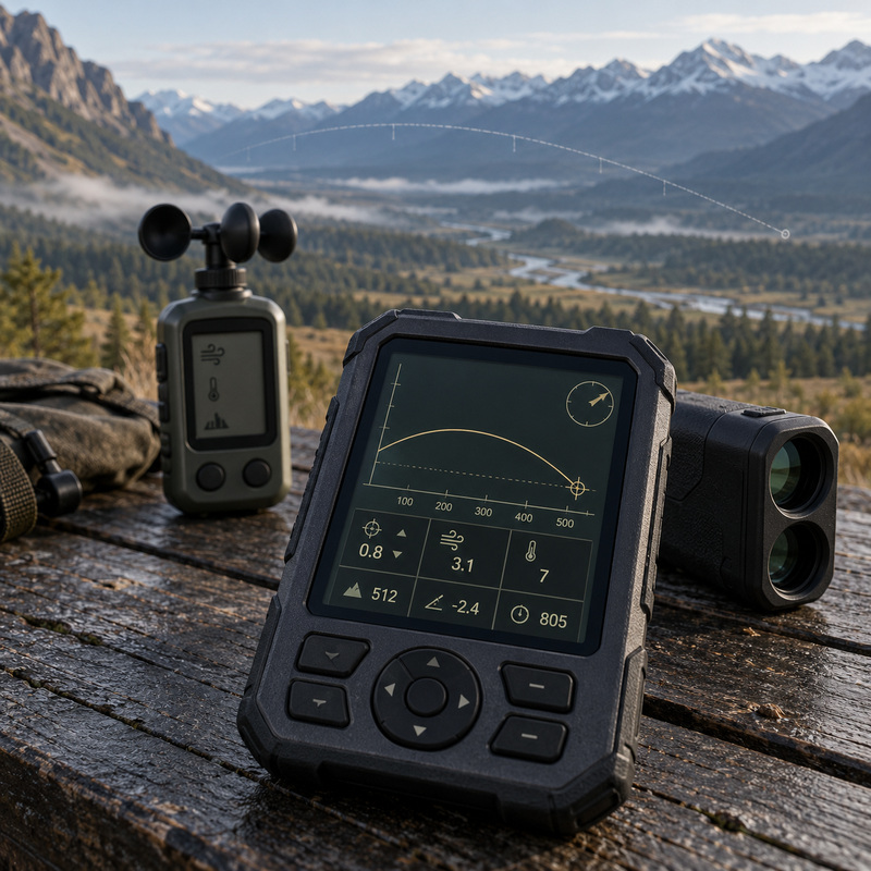
In integrated systems, the rangefinder measures distance and inclination and transmits the data to the computer. The computer then retrieves the weapon profile, acquires atmospheric conditions, and returns the correction.
Some devices can communicate with a weather station or display the solution directly in binoculars, spotting scopes, or digital viewfinders. This automation reduces manual steps, but it doesn't eliminate the need to check that the correct profile has been selected and that the laser has measured the desired target.
Check the profile on the target
The first table generated must be compared with groups taken at known distances. Before checking, it is necessary to ensure that:
- the reset is correct;
- the speed was measured with a chronograph;
- the target is at the declared distance;
- the turrets actually move the reticle by the expected amount;
- the rifle is not tilted laterally;
- wind and weather conditions have been recorded.
Any deviations must be evaluated at the center of the pattern, not at a single shot. The profile can then be calibrated by modifying only the data physically responsible for the difference.
Use in hunting activities
The calculator is particularly useful for selective hunting, open environments, and angled shots. It allows you to determine the expected correction and evaluate residual velocity and energy.
However, the presence of a numerical solution does not automatically make shooting possible. Game identification, seabed safety, position stability, obstacles, wind, and the shooter's actual skill must be considered.
The responsible distance must remain within the range in which the weapon-ammunition system maintains adequate accuracy and performance.
Mistakes and commonplaces
- “Just choose the cartridge from the archive.” Actual speed may differ from commercial speed.
- “The calculator tells you where each shot will land.” It predicts the theoretical center of the trajectory, it does not eliminate dispersion.
- “The wind measured near the shooter is valid everywhere.” Intensity and direction may change along the way.
- “More decimal places mean greater precision.” The result remains tied to the reliability of the data entered.
- “Correction makes any distance practicable.” Precision, wind, energy and safety set the real limits.
Did You Know?
- The G1 value is normally higher than the G7 because it uses a different reference bullet.
- Humid air is slightly less dense than dry air under the same conditions of temperature and pressure.
- A solution can be calculated to within one hundredth of an MRAD even if the wind has only been estimated.
- Equivalent ballistic range does not replace linear range in calculating time of flight.
Final houghts
The ballistic calculator transforms configuration and environmental data into a prediction that can be used via reticle or turrets. Its effectiveness depends not on the quantity of numbers displayed, but on the quality of the information entered and the verification of the actual trajectory.
Used correctly, it allows for a better understanding of ammunition behavior and reduces assessment errors. However, it remains a support tool: it does not replace experience, practical testing, and responsible decision-making.
EXTENDED VERSION
A ballistic calculator is a program that predicts the behavior of a bullet after it leaves the barrel. It processes data relating to the weapon, ammunition, optics, range, and atmospheric conditions to estimate drop, windage, residual velocity, energy, and flight time. The result is translated into a correction expressed in MRAD, MOA, clicks, or centimeters. It doesn't automatically predict the actual behavior of the rifle: it builds a mathematical model that becomes reliable only when the input data is correct and the profile is verified through practical tests.
In short (Italian only)
- What is it: a software that calculates the projectile's predicted trajectory.
- What data does it use: speed, ballistic coefficient, zeroing, atmosphere, distance and wind.
- What it gives back: vertical and lateral corrections, speed, energy and flight time.
- Where is it: apps, rangefinders, binoculars, viewers, and dedicated devices.
- What is the limit: An accurate forecast cannot compensate for incorrect initial data.
What does it actually calculate?
The calculator reconstructs the bullet's flight by dividing it into numerous time intervals. For each step, it determines velocity, deceleration, vertical position, and lateral displacement, repeating the process until the indicated distance is reached.
The result doesn't just represent the fall from the barrel axis. The program compares the trajectory to the line of sight , taking into account the height of the scope and the distance at which the system was zeroed.
If the solution indicates a correction of 1,8 MRAD, it means the line of sight must be adjusted by that angle using the turret or reticle. The corresponding linear measurement increases with distance: 1,8 MRAD equals 18 centimeters at 100 meters, 36 centimeters at 200 meters, and 72 centimeters at 400 meters.
How the trajectory is reconstructed
The starting point of the calculation is the position and velocity of the projectile near the muzzle. From this point on, the program applies, interval after interval, the forces that modify its motion.
At least four elements are updated in each step:
- instantaneous speed;
- the position relative to the line of sight;
- the time elapsed since exiting the barrel;
- the lateral displacement produced by the wind and any gyroscopic effects.
The new condition becomes the starting point for the next step. By repeating the process thousands of times, the software builds a numerical representation of the entire trajectory.
This system allows us to consider the fact that aerodynamic drag varies with velocity. The projectile does not lose the same number of meters per second at each stage of its flight, nor does it behave the same way through all aerodynamic regimes.
The forces acting on the projectile
After exiting the muzzle, the projectile no longer receives any thrust. Its motion is influenced primarily by gravity and air resistance.
Gravity produces a downward acceleration from the very first instant. The bullet may initially appear to be climbing relative to the aiming line because the axis of the barrel is tilted upward relative to that of the scope, not because gravity begins to act late.
Aerodynamic drag slows the projectile. As its velocity decreases, the time it takes to reach the target increases, and thus the period during which gravity and wind can exert their effects.
More advanced programs may also consider:
- drifts from the wind, produced by the movement of the air with respect to the trajectory;
- gyroscopic drift, linked to the rotation and stability of the projectile;
- Coriolis effect, determined by the Earth's rotation;
- vertical component of the wind, relevant in particular conditions;
- corner of the site, in upward or downward shots;
- target movement, if the software has the relevant function.
Three- and six-degree-of-freedom model
Most calculators intended for general use use a modified point mass model . The projectile is treated as a point with associated mass and aerodynamic properties. Its ability to overcome air resistance is described by the ballistic coefficient.
More specialized programs can use six-degree-of-freedom models, also called 6DoF . In addition to spatial displacement, they analyze rotations, attitude, precession, and dynamic behavior of the projectile.
A 6DoF model requires much more comprehensive aerodynamic data, often obtained through simulations or Doppler measurements. It is not automatically more accurate if projectile information is unavailable or does not match the ammunition used.
The main types of calculators
| Typology | Features | Main use |
|---|---|---|
| App for smartphones | Configurable, upgradeable and easily transportable | Profile creation and field use |
| Computer software | Detailed data management and trajectory comparison | Study and preparation of ballistic tables |
| Ballistic rangefinder | Measures distance and inclination, then provides the correction | Quick calculation before shooting |
| Telemetric binoculars | It combines observation, measurement and ballistic solution | Selective hunting and open territories |
| Telescope or digital viewer | View the solution directly in the observed field | Integrated aiming system |
| Handheld device | Rugged construction and dedicated environmental sensors | Professional use and harsh conditions |
Smartphone applications
Applications are the most accessible solution. They allow you to save multiple profiles, quickly edit data, and obtain comprehensive tables for various distances.
Your smartphone can acquire geographic location, inclination, and weather data from its own sensors or from connected external devices. The quality of the built-in sensors, however, isn't always sufficient for accurate weather measurements.
Before using the device in the field, it's a good idea to download maps, profiles, and the necessary data, as internet connection can be disrupted in many hunting areas. Temperature, battery life, and screen readability should also be considered.
Rangefinders and binoculars with ballistic calculation
An advanced rangefinder measures distance and angle, recalls the selected profile, and returns the correction directly. The main advantage is the reduction of manual steps: the data doesn't need to be read, transcribed, and entered into a second device.
In rangefinding binoculars, the measurement occurs during observation. Some models can receive atmospheric conditions from an external station and send the solution to a compatible spotting scope.
Integration makes the system fast, but requires careful attention to selecting the correct profile. Accidentally using data from another rifle or ammunition can generate a plausible solution on the display but a completely incorrect one on the target.
The data path
The complete operation can be summarized in this sequence:
- the rangefinder or user enters the distance;
- the system acquires inclination and atmospheric conditions;
- the program recalls the weapon and ammunition profile;
- the model reconstructs the flight of the projectile;
- the trajectory is compared to the line of sight;
- the result is converted to the selected unit;
- the correction is displayed on the screen or transmitted to the optics.
Each step represents a potential source of error. The mathematical precision of the final stage cannot correct for a distance measured in the background, an incorrect profile, or an assumed initial velocity.
Prediction and reality
The calculator describes the behavior of an ideal projectile corresponding to the entered data. Real ammunition, however, exhibits variations in velocity, concentricity, mass, and pressure. The weapon also introduces dispersion through vibrations, barrel conditions, and aiming system repeatability.
The software can predict the theoretical center of the shot pattern with great accuracy, but it cannot determine the exact location of each individual shot. Weapon dispersion and shooter error remain separate elements of the ballistic solution.
WEAPON AND AMMUNITION DATA
The quality of the ballistic solution depends primarily on the data used to describe the weapon-ammunition system. Muzzle velocity, ballistic coefficient, scope height, and zeroing distance must refer to the actual configuration used. Copying commercial values or selecting a seemingly similar cartridge can produce a credible trajectory at short ranges, but become progressively inaccurate as distance and time of flight increase.
The basic profile data
<tdgol? no. Need ensure. We can continue from table; be careful.
| Date | Function in calculation | Consequence of an incorrect value |
|---|---|---|
| Initial speed | It establishes the starting condition of the projectile | Increasing error on fall and flight time |
| Ballistic coefficient | Describes the ability to maintain speed | Slowdown calculated incorrectly |
| Resistance model | Match the projectile to an aerodynamic curve | Biased forecast in some speed regimes |
| Height of the optics | Defines the distance between the barrel axis and the sight line | Incorrect apparent trajectory |
| Zeroing distance | Establishes the point of coincidence with the line of sight | Systematically incorrect vertical corrections |
| Rifling pitch | Contributes to the calculation of stability and gyroscopic drift | Incomplete estimate of rotational effects |
| Direction of the rifling | Determine the direction of the gyroscopic drift | Lateral correction applied on the wrong side |
| Projectile mass | It intervenes in the calculation of energy and aerodynamic model | |
| Projectile mass | It intervenes in the calculation of energy and in the aerodynamic profile | Residual energy and solution associated with the wrong projectile |
| Diameter and length | They contribute to the calculation of stability | Inaccurate prediction of gyroscopic behavior |
The initial velocity
Muzzle velocity is one of the most influential parameters. It determines the time required to reach the target and affects drop, drift, and residual velocity. A seemingly modest difference can become significant over long distances.
The value shown on the ammunition packaging is obtained with a specific test barrel and under controlled conditions. The velocity produced by your rifle may vary due to:
- effective barrel length;
- chamber size;
- pitch and condition of the rifling;
- ammunition temperature;
- production batch;
- type of powder and primer;
- friction developed by the projectile;
- measuring instrument and method.
To build a reliable profile it is therefore preferable to measure the speed with a chronograph , using the same rifle and the same ammunition intended for hunting use.
How to measure speed correctly
A single reading doesn't accurately describe the ammunition's behavior. A series of shots should be recorded and at least the average velocity, standard deviation, and extreme excursion calculated.
The barrel should be in a condition consistent with its intended use. A measurement taken with a completely cold and clean barrel may produce different results than a series fired with a warm barrel or one already conditioned by several shots.
It is useful to note:
- air and ammunition temperature;
- number of shots in the series;
- speed of each shot;
- average obtained;
- cartridge or component batch;
- any abnormal readings;
- barrel condition.
The chronograph must be installed and operated according to the manufacturer's instructions. Improper alignment, incorrect muzzle clearance, or unsuitable lighting conditions can distort readings.
Mean, range and standard deviation
Average velocity is usually the value entered into the calculator. However, it doesn't indicate how much individual shots differ from each other.
The extreme range , or ES, is the difference between the highest and lowest velocities in the series. The standard deviation , or SD, describes the overall distribution of readings around the mean.
| Parameter | What does it describe? | Tools |
|---|---|---|
| Average speed | Central value of the series | Initial data of the calculator |
| Extreme excursion | Difference between faster and slower stroke | Shows the total amplitude of the change |
| Standard deviation | Distribution of speeds around the mean | Helps estimate ammunition regularity |
A small variation promotes vertical consistency over long distances. However, it doesn't automatically guarantee a tight shot pattern, as accuracy also depends on barrel vibrations, the quality of the components, and the interaction between the gun and the ammunition.
Sprint velocity and chronograph distance
Some instruments measure velocity at a short distance from the muzzle, while radar chronographs can reconstruct multiple points in the initial flight segment. The value entered into the software must match the meaning required by the program.
If the speed was measured a few meters after the sprint, it may be necessary to reset it to the starting distance using the chronograph software or a specific function. The difference is often small, but it becomes significant when seeking maximum profile consistency.
The ballistic coefficient
The ballistic coefficient , indicated by the acronym BC, expresses how effectively a projectile maintains velocity compared to a standard projectile used as a reference.
A higher value generally indicates less deceleration, but the coefficient is not an absolute measure of quality. It must be associated with the correct resistance curve and the speed range in which it is used.
Two bullets with the same nominal BC may behave differently if their shape does not correspond in the same way to the chosen model.
The G1 model
The G1 model uses a standard bullet with a flat base and a relatively short nose. It has been in use for a long time and is still common on manufacturers' bullet lists.
It can adequately describe bullets with geometry similar to the reference, but is less representative of many modern long, tapered, and tapered-base bullets.
A BC G1 is often expressed with a higher number than the corresponding G7. This does not mean that the bullet improves by changing model: they are simply two scales referring to different standard shapes.
The G7 model
The G7 model uses a reference bullet closer to the geometry of many modern long-range bullets, featuring an elongated ogive and boat tail.
For these shapes, the BC G7 tends to remain more stable across a wide velocity range and can offer more consistent prediction than the G1.
The G7, however, is not universally superior. For flat-based, relatively short, or unusual-geometric bullets, the G1 model or a specific curve may better describe actual behavior.
Comparison between G1 and G7
| Feature | G1 | G7 |
|---|---|---|
| Reference form | Shorter ogive and flat base | Elongated ogive and tapered base |
| Indicative use | Traditional bullets and numerous commercial data | Modern and aerodynamic projectiles |
| Numeric value | Generally higher | Generally lower |
| BC Stability | May vary more with some forms | Often more uniform for tapered bullets |
| Interchangeability | Values should not be transferred from one model to another | |
The ballistic coefficient is not always constant
The published BC is often presented as a single value, but the relative efficiency of the projectile can change as it moves from the supersonic to the transonic and, finally, subsonic regime.
Some manufacturers provide different coefficients for different speed ranges. A compatible calculator can automatically apply the appropriate value during each phase of flight.
Using a single medium BC may work well within typical hunting ranges, but generate increasing differences as speed approaches the transonic region.
Custom curves and Doppler data
Custom drag curves directly describe the behavior of a specific projectile rather than comparing it to a G1 or G7 model. They can be obtained using Doppler radar, which measures velocity at numerous points along the trajectory.
This data allows the software to follow the real slowdown more precisely, especially when switching between different aerodynamic regimes.
The custom curve must match the bullet's manufacturer, model, caliber, and mass exactly. A very precise curve associated with the wrong component is less useful than a good, properly selected traditional coefficient.
Mass, diameter and length of the projectile
Mass is used to calculate energy, momentum, and some stability parameters. It must be entered in the program's supported units, usually grains or grams.
Diameter and length play a role in gyroscopic stabilization calculations. Length is particularly important: for the same mass, a projectile made of less dense materials can be longer and require a faster spin.
The calculator can retrieve this data from an internal archive, but you need to check that the selected entry corresponds exactly to the component used.
Rifling pitch
The rifling twist rate indicates the distance required for the bullet to complete one complete rotation inside the barrel. A twist rate expressed as 1:10 inches means one rotation for every ten inches of advance.
The combination of pitch, velocity, diameter, length, and projectile density determines the degree of gyroscopic stabilization. An insufficient value can compromise accuracy and aerodynamic behavior.
Adequate stabilization doesn't necessarily require the fastest rotation available. The pitch must be compatible with the expected projectile range and the mechanical limitations of the component.
Rifling direction and gyroscopic drift
Rifling can be right-handed or left-handed. Most modern barrels use a right-hand twist, but this should be verified.
During flight, the stabilized bullet tends to develop a slow lateral deviation called gyroscopic drift . With a right-handed rifling, the drift is generally to the right; with a left-handed rifling, it occurs in the opposite direction.
At moderate hunting distances, the effect may be less than other variables. The calculator includes it especially in profiles intended for longer shots and when it has the necessary data to estimate it correctly.
The height of the telescope
Scope height is the vertical distance between the barrel axis and the scope axis. It is not the same as the height of the rings or the distance between the tube and the receiver of the gun.
To measure it, determine the distance between the center of the barrel and the center of the optical tube. If a direct measurement is not possible, the two dimensions can be taken separately with respect to a common reference.
This value significantly affects the relationship between trajectory and line of sight at short and medium ranges. An error of a few millimeters may be insignificant in some configurations, but it should not be ignored when building an accurate profile.
The zeroing distance
The program must know the distance at which the midpoint of impact coincides with the aiming point. It's not enough to simply enter the nominal value chosen during calibration: you need to verify that the actual zeroing is actually centered.
If the group is two centimeters higher at 100 meters, the system doesn't have a perfect zero at that distance. Some programs allow you to enter the offset directly; otherwise, the profile must be corrected by recalibrating.
Zeroing must be determined using the same ammunition described in the profile. A change in bullet, load, or batch requires at least one verification.
The temperature of the ammunition
Temperature can alter muzzle velocity because it affects the behavior of the powder and the pressure developed. The extent of the change depends on the propellant, the cartridge, and the length of time the ammunition was exposed to the environment.
The temperature of the cartridge does not always coincide with the air temperature. Ammunition left in the sun, stored in a hot vehicle, or kept close to the body may be in conditions significantly different from those indicated by the atmospheric sensor.
The most comprehensive calculators allow you to create a curve that combines temperature and velocity. This function must be based on actual measurements and not on a generic correction applied indiscriminately to each propellant.
The production batch
Two packages of the same ammunition may come from different batches and produce velocities or impact points that do not perfectly match. Industrial tolerances are usually small, but can become significant as the range increases.
For a verified profile, it's helpful to note the lot number and check the velocity when switching to a new supply. When reloading, changing powder, primer, case, or bullet should be considered a configuration change.
The profile must describe only one system
Each profile should refer to a specific combination of:
- rifle;
- barrel and relative length;
- telescope and mounting height;
- zeroing distance;
- ammunition or loading;
- bullet;
- verified average speed;
- conditions under which zero was confirmed.
If any of these changes significantly, it's best to create a new profile rather than modify the old one. Keeping separate configurations prevents you from accidentally recalling data from another weapon.
Check before saving data
Before using the profile, you should verify the units and numeric separators. A value expressed in meters per second should not be entered into a field set to feet per second; millimeters and inches are not interchangeable; grams and grains represent very different quantities.
It is also advisable to check that:
- the G1 or G7 model corresponds to the BC entered;
- the speed is the average measured one;
- the height of the optics refers to the two axes;
- zero has been confirmed on the target;
- the rifling pitch uses the correct unit;
- the direction of twist is correctly selected;
- the bullet recalled from the archive is the actual one.
Once these checks are completed, the weapon and ammunition profile is ready to be integrated with atmospheric data and ground conditions.
ATMOSPHERE, WIND AND TILT
After describing the weapon and ammunition, the calculator must know the environment in which the shot is being fired. The resistance encountered by the projectile depends on the air density , while the lateral displacement is affected by the speed and direction of the wind along the trajectory. Temperature, pressure, humidity, altitude, and inclination should not be entered as isolated data: the program combines them to determine how the deceleration, flight time, and necessary corrections will change.
The density of air
Density expresses how much mass of air is contained in a given volume. A denser atmosphere offers greater resistance to the projectile's motion; less dense air allows it to better maintain velocity.
Dense air generally increases flight time, sink rate, and wind drift. In less dense conditions, the bullet reaches the target more quickly and requires less correction.
Density isn't determined by a single parameter. It's the result of the interaction between:
- atmospheric pressure;
- temperature;
- relative humidity;
- share;
- composition of the air.
Modern computers process this information to derive an overall value. Therefore, it's inappropriate to arbitrarily adjust the altitude in an attempt to compensate for a different temperature.
Atmospheric pressure
Pressure is one of the most important parameters because it directly affects density. Higher pressure generally corresponds to a greater amount of air present in the same volume; lower pressure reduces aerodynamic drag.
The data can be expressed as:
- hectopascal or millibar;
- inches of mercury;
- millimeters of mercury;
- other units provided by the device.
Simple conversions between units are not particularly difficult. The most common error arises from confusion between absolute pressure and sea level pressure.
Absolute pressure and relative pressure
Absolute pressure, also called station pressure, is the pressure actually measured at the shooter's location. It naturally decreases with increasing altitude and is usually the most direct data to use in ballistic calculations.
The pressure reported by meteorological applications is often corrected to sea level. This processing allows comparison of atmospheric systems located at different altitudes, but it does not represent the pressure actually encountered by the projectile.
If the calculator requires absolute pressure and a value already corrected to sea level is entered along with the elevation, the effect of altitude may be counted incorrectly.
| Type of pressure | What does it represent? | Use in the calculator |
|---|---|---|
| Absolute pressure | Value actually measured at the user's position | It can be inserted directly without adding the quota, according to the software |
| Sea level pressure | Correct value for meteorological use | It must be associated with the quota if the program provides for this modality |
| Barometric altitude | Quota obtained from pressure according to a standard atmosphere | It does not necessarily coincide with the geographical altitude |
The air temperature
At the same pressure, warm air is less dense than cold air. At higher temperatures, the projectile generally encounters less resistance and maintains its velocity better.
Temperature also affects the speed of sound. This is important as the projectile approaches the transonic region, because the Mach number depends on the ratio between its speed and the speed of sound in the environment it passes through.
The value should represent the air conditions along the trajectory. A sensor exposed to the sun or held close to the body may indicate a significantly different temperature than the actual one.
Air and ammunition temperature
These two values should not be confused. Air temperature affects atmospheric density and the speed of sound; ammunition temperature can affect pressure and muzzle velocity.
Cartridges carried in an inside pocket, left in a vehicle, or exposed to direct sunlight may be at a different temperature than the ambient temperature. The calculator can only handle these two effects separately if it has the relevant fields and a verified velocity-temperature curve.
Relative humidity
Humidity has a lesser influence than pressure and temperature, but it can be included in more accurate profiles. Contrary to popular belief, humid air is slightly less dense than dry air under the same temperature and pressure conditions.
Water molecules actually replace some of the nitrogen and oxygen molecules, which have a higher molecular mass. Increased humidity therefore tends to reduce aerodynamic drag, albeit moderately.
At normal hunting distances, an error in humidity generally has much less consequence than an incorrect assessment of wind or initial speed.
The altitude
As you gain altitude, atmospheric pressure decreases and the air becomes less dense. All other things being equal, the projectile maintains velocity better and requires less vertical correction.
Geographic altitude should not be treated as an independent force. It is used by the program to estimate pressure when an absolute measurement is not provided.
If the device already receives a real and correct pressure, entering the measurement at the same time may be superfluous or produce a duplication, depending on the logic of the software used.
Density altitude
The density altitude translates actual atmospheric conditions into the altitude at which the same density would be found in a standard atmosphere.
A location located at 1.000 meters may have a much higher density altitude on a hot day with low pressure. On a cold day with high pressure, however, the value may be lower than the geographic altitude.
This parameter allows you to represent the combined effect of temperature, pressure, and, to a lesser extent, humidity with a single number. It's useful when the calculator accepts the density altitude directly, but it shouldn't be entered along with the atmospheric data itself if the program would process it a second time.
Standard conditions and actual conditions
Commercial ballistic tables are often compiled using a standard atmosphere. In the field, conditions can be very different.
| Environmental variation | Effect on density | General consequence |
|---|---|---|
| Temperature rising | It decreases | Less slowdown |
| Absolute pressure on the rise | Increase | Greater slowdown |
| Increasing share | It decreases | More tense trajectory |
| Humidity rising | It decreases slightly | Generally limited effect |
The differences become more significant as distance increases and the bullet slows. Within moderate ranges, other factors may have a greater impact.
How to measure atmospheric data
A portable station can provide temperature, pressure, humidity, and air density. To obtain reliable readings, it must be allowed to acclimatize and kept away from heat sources.
The sensor should not be held in the palm of your hand for extended periods, placed on the hood of a hot vehicle, or exposed to direct sunlight. Even the user's breathing can temporarily alter the temperature and humidity.
The conditions measured at the shooting position do not necessarily describe the entire trajectory, especially when the target is much higher, lower, or at a great distance.
The wind as a dynamic variable
Wind is often the most difficult component to evaluate because it can vary in strength and direction between the shooter and the target. The calculator performs the mathematical operation correctly, but it can't know what's happening along the path if the data entered doesn't represent it.
A uniform wind is relatively simple to model. In reality, valleys, forests, rocks, buildings, and terrain variations produce accelerations, vortices, and areas of relative calm.
The lateral solution should therefore be interpreted as the consequence of the wind described by the user, not as a complete measurement of the atmosphere passed through.
Wind speed and direction
Speed can be expressed in meters per second, kilometers per hour, miles per hour, or knots. Before entering the unit, you should check the selected unit.
Direction is frequently described through the clock system:
- wind from 12 o'clock: frontal;
- wind from 6 o'clock: rear;
- wind from 3 o'clock: lateral from the right;
- wind from 9 o'clock: lateral from the left;
- intermediate directions: oblique wind.
It's crucial to specify whether the application asks for the wind direction or the wind direction . Confusing the two conventions inverts the correction.
The actual value of the wind
Not all wind blows perpendicular to the trajectory. The lateral component depends on the angle at which the flow meets the line of fire.
A perfectly lateral wind has full value. An oblique wind produces a smaller transverse component; a frontal or rear wind affects flight time primarily, with a generally smaller vertical effect.
| Indicative direction | Lateral component | Prevailing effect |
|---|---|---|
| 3 or 9 pm | Milk | Maximum lateral drift |
| 1:30, 4:30, 7:30, or 10:30 | About 70% | Reduced lateral drift |
| 1, 5, 7 or 11 o'clock | About 50% | Moderate drift |
| 12 or 6 pm | Almost nothing | Flight time variation |
These percentages represent a useful simplification. The calculator uses trigonometric functions and can calculate more precise angles.
Near wind and far wind
The wind present in the first part of the trajectory exerts a particular influence because it changes the projectile's direction early. The initial deviation continues to develop throughout the rest of the flight.
Wind near the target, on the other hand, acts on a slower projectile, making it more exposed for each meter traveled. The relative importance of the different traits depends on the configuration and cannot be reduced to a rule that applies in every situation.
Some calculators allow you to create multiple wind zones, assigning different intensities and directions to the various segments of the trajectory.
How to observe the wind
The anemometer measures the wind at the user's location, but along the way other clues need to be interpreted:
- movement of grass, leaves and branches;
- dust or snow thrown up;
- smoke and suspended particles;
- undulation of vegetation;
- mirage observed through optics;
- recognizable variations on the different sides.
These indications require experience and don't always provide an exact velocity. They help determine whether the value measured at the shooting position is representative or whether the flow changes along the path.
Il miraggio
A mirage is caused by variations in the refractive index of air caused by layers of different temperatures. Through a telescope, it appears as a wave-like motion of the image.
The direction of the ripple can help assess the wind in the vicinity of the focus area. A near-vertical mirage suggests a reduced lateral component; a tilted or horizontal movement indicates a stronger flow.
Interpretation can be complicated by the heat of the reed, heated ground, and the presence of different atmospheric layers.
The vertical component of the wind
Updrafts and downdrafts can develop along slopes, rock faces, and valleys. Some calculators allow you to include a vertical component, but this is difficult to measure accurately.
Vertical wind should not be confused with the difference in trajectory due to the angle of the airplane's position. In the first case, it is the movement of the air that changes the flight; in the second, it changes the geometry with respect to gravity.
Aerodynamic wind and gyroscopic drift
Wind drift is distinct from gyroscopic drift . The latter arises from the interaction between rotation, stability, and trim of the projectile, even in the absence of crosswinds.
With right-handed rifling, the bullet generally tends to deflect to the right; with left-handed rifling, to the left. The degree of deflectance increases with flight time and depends on spin rate, stability, and aerodynamic characteristics.
The calculator must prevent this component from being counted twice. If gyroscopic correction is activated, it must not be artificially incorporated into the wind value.
The Coriolis effect
The Coriolis effect arises from the Earth's rotation. Since the shooter and the target are on a moving surface, the trajectory appears slightly deviated from the Earth's system.
The calculation requires:
- latitude;
- direction of fire with respect to north;
- distance;
- flight time;
- projectile velocity.
The effect can have both a lateral and a vertical component. At normal hunting distances, it is generally much smaller than the error produced by an imperfect wind assessment. It becomes especially significant as flight time and distance increase.
Entering an incorrect geographic direction may result in a correction in the opposite direction. This function should only be activated when the orientation and position are known with sufficient precision.
The tilted shot
When the target is above or below the shooter, the distance measured along the line of sight does not coincide with the horizontal component.
In a simplified geometric description:
Horizontal distance = linear distance × cosine of angle
A target placed at 400 meters with a 30-degree incline has a horizontal component of approximately 346 meters. Using the correction provided for 400 meters on flat terrain would typically result in overcompensating for the drop.
Linear distance and equivalent distance
| Size | Meaning | Use |
|---|---|---|
| Linear distance | Direct path between instrument and target | Flight time, energy and wind action |
| Horizontal distance | Projection of the shooting line on the horizontal plane | First approximation of the gravitational effect |
| Equivalent ballistic distance | Value processed by the device for vertical correction | Simplified management of inclined shooting |
Equivalent ballistic range doesn't replace linear range in any calculation. The projectile travels the entire distance: flight time, velocity loss, and wind drift still depend on the actual range.
The limits of the cosine rule
The cosine rule is useful for understanding the problem and offers a good approximation in many situations. However, it doesn't describe every aspect of canted shooting.
A complete model also considers:
- relative height between starting point and target;
- atmospheric density along the path;
- vertical component of the initial velocity;
- flight time over actual distance;
- rotational effects;
- geographical orientation.
For sharp angles and long distances, a calculator that directly integrates the inclined trajectory can offer a better prediction than the equivalent horizontal distance alone.
Angle expressed in degrees or percentage
The slope can be expressed in degrees or as a percentage of the slope. The two values are not equivalent.
A slope of 100% corresponds to an angle of 45 degrees, not 90. If the program requires degrees and a percentage is entered, the solution will be incorrect.
Rangefinders equipped with an inclinometer normally transmit the value in the format expected by their system, reducing the risk of manual conversion.
Measurement in the shooting position
Environmental data must be collected at the location from which the observation will be made. Altering altitude, changing slopes, or waiting too long can affect pressure, temperature, and wind.
Before accepting the solution it is advisable to check:
- that the sensor is acclimatized;
- that the pressure used is of the required type;
- that the wind is inserted with the correct direction;
- that linear distance and inclination come from the same measurement;
- that the app is not using remote or out-of-date weather data;
- that the units match those selected in the profile.
When to update your terms
Temperature and pressure generally change more slowly than the wind. It's not necessary to update them after every observation if conditions remain stable, but they should be checked when a long time passes or the altitude changes significantly.
Wind, on the other hand, requires constant evaluation. Its intensity and direction can change even in the few seconds between measurement and shot.
The calculator provides a mathematical snapshot of the entered conditions. The more variable the environment, the more quickly that snapshot can become outdated.
The most accurate data is not always the most important
Entering humidity very precisely offers limited benefit if the initial velocity is only estimated or the wind has an uncertainty of several meters per second.
The quality of the profile must be built by assigning priority to the variables with the greatest influence:
- actual target distance;
- wind speed and direction;
- initial velocity verified;
- correct resistance coefficient or curve;
- pressure and temperature;
- inclination;
- humidity and side effects.
The order may change based on distance, trajectory, and conditions, but it helps to understand why a long series of decimal values alone does not guarantee a reliable solution.
SOLUTIONS, RETICLE, TURRETS AND DEVICES
After processing the weapon, ammunition, and environmental data, the calculator returns a ballistic solution . This can be expressed as an angular correction, linear displacement, number of clicks, or a reference to be used in the reticle. To interpret it correctly, it is necessary to understand that bullet drop, scope adjustment, and aiming point position are not the same thing, even when they are represented in the same table.
The results provided
| Outcome | What does it indicate? | Tools |
|---|---|---|
| Vertical correction | Angle needed to compensate for the trajectory | Adjusting the turret or reference in the reticle |
| Lateral correction | Expected angle for wind and rotational effects | Horizontal compensation |
| Linear fall | Vertical deviation expressed in centimeters or inches | Understanding the trajectory |
| Residual speed | Expected speed at the indicated distance | Flight regime evaluation |
| Residual energy | Kinetic energy still possessed by the projectile | Terminal performance analysis |
| Flight time | Time elapsed since exiting the barrel | Wind and target motion evaluation |
| Mach number | Ratio between bullet speed and speed of sound | Identification of supersonic and transonic regimes |
| Lead | Theoretical advance on a moving target | Specialized function, dependent on lateral velocity |
Fall and vertical correction
Drop can be described as the vertical distance between the bullet and a reference line. Correction, on the other hand, indicates the angle by which the line of sight must be changed.
Two programs may display different linear values if they use different references, even though they suggest the same angular correction. It is therefore necessary to check whether the table represents:
- fall with respect to the initial axis of the barrel;
- deviation from the line of sight;
- correction from zeroing;
- position of the projectile on the trajectory;
- movement to be applied to the turret.
For practical use with a riflescope and reticle, the angular correction is usually the most easily transferable data.
MRAD and milliradians
The milliradian is a unit of angle. One MRAD subtends a measurement equal to one thousandth of the distance:
- 1 centimeter at 10 meters;
- 10 centimeters at 100 meters;
- 20 centimeters at 200 meters;
- 50 centimeters at 500 meters;
- 1 meter at 1.000 meters.
A turret with 0,1 MRAD clicks theoretically moves the point of impact one centimeter at 100 meters and five centimeters at 500 meters.
The term "mil" is often used as an abbreviation for milliradian. It should not be confused with the millimeter, which is a linear unit.
MOA and minutes of angle
The minute of angle , or MOA, is one sixtieth of a degree. One MOA subtends approximately 2,91 centimeters at 100 meters.
In practical use, it's sometimes approximated to three centimeters, but the difference increases with distance. At 1.000 meters, one MOA corresponds to approximately 29,1 centimeters, not exactly 30.
A ¼ MOA turret theoretically produces a movement of approximately:
- 0,73 centimeters at 100 meters;
- 1,45 centimeters at 200 meters;
- 2,91 centimeters at 400 meters;
- 7,27 centimeters at 1.000 meters.
Comparison between units
| Unit | Typology | Value at 100 meters | Use |
|---|---|---|---|
| 1 MRAD | Angular | 10 cm | Metric reticles and turrets |
| 0,1 MRAD | Angular | 1 cm | Frequent value of a click |
| 1 MOA | Angular | About 2,91 cm | Reticles and turrets in angle minutes |
| ¼ MOA | Angular | About 0,73 cm | Frequent value of a click |
| Centimeters | Linear | Direct value | Description of the deviation on the target |
| Click | Mechanics | It depends on the turret | Operational adjustment of the telescope |
Angular units and linear measures
MRAD and MOA remain constant as angles, while the corresponding linear measurement increases with distance. Centimeters describe a valid displacement only at the distance for which they were calculated.
If the table indicates a correction of 40 centimeters at 400 meters, that value cannot be directly transferred to 500 meters. Converting it to 1 MRAD instead provides an angular reference that can be used via the turret and reticle.
This is why angular units are particularly suitable for managing corrections.
From correction to number of clicks
The number of clicks is obtained by dividing the correction by the value of each click. If the program indicates 2,4 MRAD and the turret moves 0,1 MRAD per click:
2,4 ÷ 0,1 = 24 clicks
With a 6 MOA correction and a ¼ MOA turret:
6 ÷ 0,25 = 24 clicks
The calculation is simple only if the turret's nominal value corresponds to the actual movement. A mechanically imprecise adjustment can accumulate errors when numerous corrections are applied.
Correct with turrets
Rotating the elevation turret changes the orientation of the internal optical group, shifting the line of sight relative to the telescope's axis. The windage turret performs the same function on the horizontal plane.
The main advantages of mechanical correction are:
- constant use of the center of the grid;
- less crowded field of vision;
- ability to apply precise values;
- immediate reading of the set solution.
Before you operate, you need to know the direction indicated on the turret. The words UP, DOWN, LEFT, and RIGHT usually describe the movement of the point of impact, not the visible movement of the reticle.
Zero stop and return to zero
The zero stop is a mechanical stop that prevents the turret from moving beyond the zeroing position. After an elevation adjustment, it allows you to quickly return to the starting point without counting clicks.
Some systems allow you to slightly exceed zero to handle particular situations; others stop exactly at the set position.
The zero stop does not guarantee the accuracy of the turret. It serves to find a mechanical reference and should only be configured after zeroing is complete.
RPM and rotation indicator
Turrets with long travel may require multiple full rotations. Confusing the first turn with the second means applying a correction that is significantly different from the intended one.
More advanced models use visual or tactile indicators that show the number of rotations. The calculator can also display the correction as a combination of rotations and clicks remaining.
Before using it, you need to know how many MRAD or MOA correspond to a full rotation.
Correct with the grid
As an alternative to turrets, you can use internal graduations by keeping the center of the reticle offset from the point you want to hit. This technique is often called holdover for vertical correction and wind hold for lateral correction.
If the calculator indicates 1,6 MRAD of elevation and 0,5 MRAD of wind, the corresponding grid point is placed on the target.
The system allows you to:
- apply the solution quickly;
- avoid modifying the mechanical zero;
- adapt to sudden changes in wind;
- combine vertical and lateral correction.
However, it requires a correctly graduated reticle and a perfect knowledge of its symbols.
First focal plane
In a first focal plane reticle , the graduations change apparent size along with the image. Their angular value therefore remains constant at each magnification.
A correction of 2 MRAD can be applied using the same notch at both 6x and 15x. This behavior makes the system particularly suitable for direct use of the calculator solutions.
At minimum magnification, however, the finer references can become difficult to read; at maximum, the thicker lines can cover a significant portion of the target.
Second focal plane
In the second focal plane , the reticle maintains a constant apparent size while the image changes with magnification. The graduations have the declared value only at the power specified by the manufacturer.
If a reticle is calibrated at 12x and used at 6x, the portion of the target between the notches changes. The calculator can only account for this difference if it knows the actual magnification and the specific behavior of the reticle.
To avoid errors, it is preferable to use the pot provided for calibration or apply the correction using the turrets.
Consistency between reticle and turrets
A system that's entirely MRAD or MOA makes for immediate reading. If an impact is observed 0,7 MRAD to the right, the correction is also 0,7 MRAD on the turret.
A scope with an MRAD reticle and MOA turrets can be used, but requires conversion. The calculator reduces the math overhead, but does eliminate the risk of reading or setting the wrong unit.
For quick use it is preferable to keep the same unit in the software, reticle, turrets and personal annotations.
Dedicated ballistic reticles
Some reticles use references associated with predetermined distances rather than a uniform angular scale. The software can indicate which symbol to use with a given trajectory.
The correspondence depends on:
- zeroing distance;
- initial velocity;
- ballistic coefficient;
- height of the optics;
- magnification, in SFP models;
- weather.
The marks marked 200, 300 or 400 meters do not necessarily maintain the same correspondence when changing ammunition or conditions.
The ballistic table
The calculator can generate a table with user-selected ranges. A hunting table might show, for each distance:
- correction in MRAD or MOA;
- drift with a reference wind;
- residual speed;
- residual energy;
- flight time;
- possible reference in the grid.
Too large intervals require interpolation. Too small intervals produce a long, difficult-to-navigate table. The subdivision should reflect the actual distances used.
The quick card on the weapon
The essential values can be recorded on a small waterproof card attached to the stock, to the lens cap or kept in the optics case.
The form must contain only the essential information and clearly specify:
- weapon and ammunition;
- zeroing distance;
- unit used;
- reference atmospheric conditions;
- corrections to the main distances.
A table without the profile indication can easily be confused with that of another rifle.
Residual speed and energy
Residual velocity indicates how fast the projectile is moving at the selected distance. It is used to determine flight time, aerodynamic regime, and energy.
Kinetic energy depends on mass and the square of the velocity. A reduction in velocity therefore produces a more than proportional decrease in energy.
The calculated value alone does not describe terminal effectiveness. Expansion, penetration, and behavior on game also depend on the bullet's construction and the velocity range for which it was designed.
The Expansion Threshold
Some manufacturers specify a minimum velocity required to achieve the expected expansion. The calculator can show the distance at which the bullet falls below that threshold.
This data should be interpreted with caution. The terminal response depends on the target's resistance, impact angle, tip deformation, and manufacturing tolerances.
The theoretical distance at which sufficient speed remains does not automatically correspond to a responsible hunting distance. Accuracy, energy, wind, stability of position, and the ability to correctly identify game must also be considered.
Flight time
Time of flight determines how long the projectile is exposed to gravity and wind. It also affects the lead required for a moving target.
A difference of a few tenths of a second can produce a significant shift if the target changes direction or velocity. Therefore, lead calculation functions should be considered estimates based on regular motion.
An animal does not move like a mechanical target: it can stop, accelerate or change direction during its flight.
Supersonic and transonic regime
The Mach number compares the speed of the projectile to the speed of sound under current atmospheric conditions. The transonic region does not correspond to a single value, but rather to a range in which the flow around the projectile progressively changes.
During this transition, resistance and dynamic stability can change. Properly designed projectiles pass through the region more consistently, while others may exhibit increased dispersion.
The computer can predict when the transition will occur, but it cannot determine with absolute certainty how each individual bullet will react.
Connection with the laser rangefinder
The rangefinder provides linear distance and, in models equipped with an inclinometer, the angle of inclination. This data can be automatically sent to the integrated calculator or a connected application.
The system recalls the selected profile, acquires the atmospheric conditions, and returns the correction. The entire process can take just a few moments.
Speed doesn't eliminate the need to double-check that the laser has measured the correct target. Branches, vegetation, terrain, and the background can all generate different readings.
Connection to a weather station
A portable station can transmit temperature, pressure, humidity, wind direction, and wind speed via Bluetooth. Automatic transfer prevents transcription errors.
However, the measured wind remains the one present near the sensor. The digital connection makes the local data precise, but not necessarily representative of the entire path.
Before use, you should check that the connection is active, that the values are up to date, and that the application is not using a previously stored reading.
Communication with the telescope
Some ecosystems transmit the solution to a compatible telescope. The correction can be presented through a light spot, an indicator on the display, or a digital reference.
In traditional riflescopes, the system doesn't physically move the reticle: it generally displays a point corresponding to the solution. In digital devices, however, it can change the graphical position of the aiming reference.
The user must know which parameter is being transferred, which profile is active and whether the correction includes wind, tilt and secondary effects.
Complete solution and simplified solution
Some devices only display vertical correction; others also display drift, velocity, energy, and flight time. A large amount of information isn't always beneficial in operational terms.
The ideal screen should make it immediately recognizable:
- measured distance;
- correction unit;
- vertical value;
- possible lateral correction;
- weapon-ammunition profile used.
Analysis data can be viewed separately without overloading the main display.
Checks before applying the solution
Before rotating the turrets or using the reticle notches it is advisable to check:
- that the selected profile matches the weapon and ammunition;
- that distance and inclination are updated;
- that MRAD, MOA or clicks match the optics system;
- that the wind is inserted in the correct direction;
- that the turret starts from the zero position;
- that the number of turns is clearly identified;
- that the reticle is used at the correct magnification when placed in the second focal plane.
These checks take a few seconds and prevent errors much larger than those produced by normal approximations of the mathematical model.
PRACTICAL VERIFICATION, HUNTING USE AND ERRORS
A ballistic profile isn't complete when the calculator produces the first table. It must be compared with the actual behavior of the weapon and ammunition. The verification phase allows us to identify errors in the initial data, check the turret accuracy, and adapt the prediction to the actual configuration used. Only after this operation can the solution become a reliable tool in the field.
Construction of the ballistic profile
The procedure must begin with the precise identification of the weapon-ammunition combination. Each profile should be associated with a single configuration and have an easily recognizable name.
Before generating the table you need to record:
- model and caliber of the rifle;
- barrel length and rifling pitch;
- direction of the rifling;
- projectile model and relative mass;
- measured average initial velocity;
- ballistic coefficient and G1, G7 or custom curve;
- height between the axis of the barrel and the axis of the telescope;
- distance and conditions of resetting;
- reticle and turret units;
- reference atmospheric conditions.
The profile must be saved with a name that allows it to be immediately distinguished from other profiles. The caliber name alone is not enough, as cartridges of the same caliber can use very different bullets and velocities.
The zeroing verification
Before checking the trajectory at longer distances, you must ensure that the average point of impact actually coincides with the aiming point at the zeroing distance.
The test must be performed through a grouping, not based on a single hole. Every weapon has a natural dispersion pattern, and a hit could be the result of chance.
If the center of the shot does not coincide with the expected point, it is possible to:
- mechanically correct the telescope;
- insert the actual deviation into the program, if the function is available;
- repeat the test to verify that the movement is stable.
An error present at zero is transferred to all subsequent distances and must not be compensated for by improperly modifying other parameters.
Check the accuracy of the turrets
The value indicated on a turret is nominal. A 0,1 MRAD click should move the point of impact by four inches at 100 meters after ten clicks, but the correspondence must be verified.
The check can be performed using a graduated target and a perfectly stable optic. A known correction is applied and the actual displacement of the reticle or midpoint of impact is measured.
The most comprehensive tests evaluate:
- correspondence between nominal clicks and actual movement;
- regularity throughout the excursion;
- return to starting position;
- no games or delayed movements;
- consistency between vertical and lateral adjustment.
If the calculator produces a correct solution but the turret does not apply it faithfully, the result on the target will still be incorrect.
The progressive distance test
After confirming the reset, the trajectory should be checked over several distances. It's best to proceed gradually, starting from an intermediate value and only then reaching the expected maximum.
| Phase | Control | Target |
|---|---|---|
| Zeroing | Midpoint of impact | Confirm the initial reference |
| Intermediate distance | Comparison between forecast and squad | Identify obvious errors in data |
| High distance | Vertical and lateral deviation | Evaluate error growth |
| repetition | New rosés in known conditions | Separating the real trend from random dispersion |
| Final confirmation | Trajectory after corrections | Validate the final profile |
Each test must be carried out on a shooting range or in an authorized area, respecting safety regulations and using targets placed at known distances.
Comparing prediction and reality
The deviation must be evaluated at the center of the group. If a group is higher or lower than expected, it is necessary to determine whether the difference is systematic or caused by normal dispersion.
It is useful to record for each series:
- effective distance;
- correction applied;
- position of the midpoint of impact;
- size of the shot;
- temperature and pressure;
- estimated wind;
- velocity of the ammunition, if measured again;
- barrel condition and shooting position.
A single abnormal pattern doesn't necessarily justify a profile change. The result must be repeatable.
Profile truing
Truing refers to the process by which the calculated trajectory is adapted to the actual observed impacts. The program modifies one or more parameters within plausible limits to match the prediction with actual behavior.
The procedure must be performed only after having verified:
- reset;
- target distance;
- initial velocity;
- height of the optics;
- turret accuracy;
- absence of significant canting;
- weather conditions entered;
- quality and position of the shot.
Truing should not be used to hide a mechanical error, an incorrect measurement, or irregular ammunition.
Which data to correct?
At ranges where the projectile remains largely supersonic, a progressive vertical difference may be due to a non-representative initial velocity. In this case, some programs allow you to obtain a calibrated velocity.
When the difference is especially noticeable at very long ranges or near the transonic region, the drag curve may be involved. Advanced software can correct for an aerodynamic factor or choose a more suitable custom curve.
The modification must remain physically credible. If the program requires a speed that is significantly different from the measured one, the problem likely lies elsewhere.
Why not arbitrarily change the BC?
Changing the ballistic coefficient to match a single impact is a quick but potentially deceptive method. The ballistic coefficient controls the retardation along the entire trajectory, and an improper adjustment can correct one distance while introducing errors in all the others.
Before intervening, it is necessary to make sure that the G1 or G7 model is correct and that the published value refers exactly to the bullet used.
When available, a specific Doppler curve is preferable to a fitted coefficient without a verifiable criterion.
The actual distance of the target
A ballistic test is only valid if the distance is precisely known. The shooting range markings should be checked when seeking a very accurate match.
A rangefinder can provide a reliable measurement, provided it is used on a sufficiently reflective and stable target. At long distances, it is advisable to repeat the reading and check that the beam does not hit the ground or background.
An error in range is easily attributed to the ballistic coefficient or velocity, producing incorrect profile corrections.
The canting of the weapon
Canting is the lateral inclination of the weapon relative to the vertical. When the scope is rotated along with the rifle, the correction set on the elevation turret no longer acts exclusively on the vertical plane.
Part of the displacement becomes lateral and the trajectory deviates from the intended plane. The effect increases with:
- tilt angle;
- height of the optics;
- distance;
- amount of vertical correction.
A level can help keep the system properly oriented, but it must be installed in relation to the grid and the action, not simply aligned to an external surface that may not be perfectly orthogonal.
Create a verified table
After comparing the calculations and impacts, a final table can be generated. This should contain the actual useful distances and a limited amount of immediately readable information.
For a hunting table the following may be sufficient:
- distance;
- vertical correction;
- drift for a reference wind;
- residual speed;
- residual energy;
- possible reference in the grid.
It's a good idea to clearly indicate the profile, unit, reset, and reference atmospheric conditions. The date of the last check helps identify tables that are no longer up-to-date.
Update your profile
The profile must be checked when a component capable of influencing the impact point or trajectory is modified.
| Modification | Necessary control |
|---|---|
| New batch of ammunition | Speed, pattern and zeroing |
| Different weight or model of bullet | New full profile |
| Change of charge | Speed, pressure and trajectory |
| Replacing the scope or mounts | Optics height and zeroing |
| Adding or removing a moderator | Point of impact, speed and accuracy |
| Replacing the barrel | Remeasurement of all key data |
| Marked seasonal variation | Speed and weather conditions |
Keeping separate versions allows you to compare results without losing the previous profile.
Use in selective hunting
In selective hunting, the calculator allows you to determine the expected correction after measuring distance, angle, and environmental conditions. Its usefulness increases in open spaces and when the trajectory presents deviations that cannot be ignored.
However, the mathematical solution represents only one element of the decision. Before shooting, the following must be evaluated:
- certain identification of the wild animal;
- presence of a safe seabed;
- stability of position;
- obstacles along the firing line;
- wind and its variability;
- residual energy and speed;
- actual ability of the shooter;
- time available to carry out all checks.
Mountain employment
In mountain environments, the calculator is particularly useful for managing slopes, altitude differences and weather conditions different from those of the zero setting.
Valleys can generate complex winds, updrafts, and variations between sunny and shaded slopes. A reading taken next to the shooter doesn't necessarily describe the entire course.
Tilt can be accurately measured with a rangefinder, while wind requires observation and experience. The seemingly most precise reading on the display isn't always the most uncertain variable.
Use in the forest
At short ranges, ballistic correction may be modest, but the height of the scope and the presence of obstacles close to the firing line become important.
A branch observed through the telescope may be out of focus and difficult to see. The computer cannot detect vegetation, bottom security, or deviations caused by an obstacle.
In a complex environment, the priority remains the direct reading of the scene, not the quantity of available data.
Ballistically possible distance and responsible distance
The software can produce a solution even for distances beyond the capabilities of the shooter, the weapon, or the projectile. The presence of a numerical value does not automatically make the shot practicable.
The responsible distance must remain within a range in which it is possible to:
- maintain an adequate spray pattern in the vital zone;
- evaluate the wind with sufficient reliability;
- maintain velocity and energy compatible with the projectile;
- correctly identify the subject;
- avoid risks arising from movement and flight time;
- have a stable support and a safe bottom.
The maximum technical distance must be established through realistic tests, not by simply reading the table.
Complete practical procedure
- Accurately identify your rifle, barrel, optics and ammunition.
- Measure the initial velocity through a representative series.
- Select the correct coefficient and G1, G7 or custom pattern.
- Measure the height between the axis of the barrel and the axis of the telescope.
- Confirm the midpoint of impact at the zeroing distance.
- Check the value, regularity and return of the turrets.
- Enter pressure, temperature, humidity and inclination in the required format.
- Measure the distance and evaluate the wind along the route.
- Generate the first ballistics table.
- Compare the forecast with shots taken at progressive distances.
- Correct only the parameter physically responsible for the deviation.
- Repeat the test and confirm the profile.
- Create a summary table with clearly indicated units and configuration.
- Update your profile when a relevant component changes.
Mistakes and commonplaces
- “The calculator tells you exactly where the bullet will hit.” It provides a forecast based on the entered data and does not eliminate system dispersion.
- “You just need to choose the cartridge from the archive.” Actual velocity and point of impact may differ from commercial values.
- “The ballistic coefficient is always constant.” Relative efficiency may change at different speeds.
- “The compensated distance replaces the real one.” Flight time, energy and wind depend on the complete path.
- “The wind measured next to the shooter is valid along the entire trajectory.” Soil and vegetation can radically change it.
- “More decimal places mean greater precision.” A detailed numerical representation may result from unreliable data.
- “Truing automatically corrects any mistakes.” It can also hide an incorrect range or an inaccurate turret.
- “The residual energy alone determines the effectiveness.” The terminal behavior of the projectile at impact velocity also matters.
- “The solution makes any shot possible.” Stability, safety, wind and shooter skill remain crucial.
How to recognize a quality calculator
A good program should clearly explain what data it's using and allow you to monitor it. A simple interface shouldn't obscure the unit, resistance pattern, or the nature of the corrections displayed.
Among the most important features are:
- support for G1 and G7 coefficients;
- possible use of custom curves;
- correct management of absolute pressure and altitude;
- ability to enter measured data;
- calculation of inclined shots;
- management of gyroscopic drift and Coriolis effect;
- guided and transparent truing;
- saving separate profiles;
- clear selection of units;
- export of summary tables;
- works even without a connection;
- compatibility with external rangefinders and sensors;
- verifiable updates to bullet libraries.
Quality must also be assessed in error handling. The software should flag unlikely values, incompatible units, and missing essential fields.
Reliability of connected devices
An integrated system relies on a rangefinder, weather sensor, wireless connection, battery, and software. A single component failure can prevent the solution from being achieved.
It is advisable to have:
- an essential table already verified;
- a manual method for using the reticle;
- batteries adequately charged;
- knowledge of the main functions even without a connection;
- periodic check of updates and saved profiles.
Technology must reduce steps and errors, not create a dependency without alternatives.
Did You Know?
- A solution can be mathematically accurate to one hundredth of an MRAD even though it derives from a wind estimate with a much larger uncertainty.
- The G1 value generally appears higher than the G7, but does not indicate superior performance: it changes the standard reference bullet.
- Absolute atmospheric pressure may make entering altitude unnecessary, depending on the method used by the software.
- A turret that makes a small error per MRAD can accumulate a significant deviation when large corrections are applied.
- The Coriolis effect can be calculated with considerable accuracy, but at hunting distances it is often less than the error caused by a small change in wind.
Final houghts
The ballistics calculator transforms the characteristics of the weapon, ammunition, and the atmosphere into a trajectory prediction. Its accuracy depends not only on the complexity of the program, but above all on the quality of the data and the verification performed on the target.
Measured airspeed, a correct aerodynamic model, true zeroing, and a wind reading form the foundation of the profile. More advanced functions, such as gyroscopic drift, Coriolis, and Doppler curves, become useful only after these elements have been mastered.
Used correctly, the calculator allows you to better understand the limitations of your weapon-ammunition combination and avoid improvised compensations. It doesn't replace experience, safety, and responsibility: it offers a numerical solution, while the decision whether to fire remains with the user.